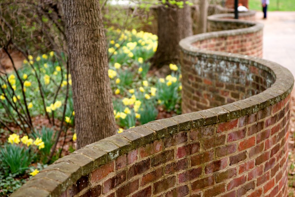
A serpentine wall, or crinkle crankle wall, may seem like a surprising structure to use for fences, but may end up being more efficient in terms of building material than a straight fence which must withstand the same horizontal forces.
In a post which is the raison d’etre for this one, John D. Cook derives a formula for computing the arc length of a sinusoidal curve. By assuming that such a sinusoidally-shaped wall could withstand lateral forces as much as a straight wall would, had the straight wall been twice as thick, he shows that you could save bricks in fencing off the same perimeter with a serpentine wall.
However, I found this implicit physical assumption to be quite unsatisfying. Why would a serpentine wall be as strong as a straight one twice as thick? Why should it be sinusoidal?
In this blog post, I inspect these questions with idealized but explicit physical assumptions and use them to explore what would the optimal shape of a wall be, given a fixed amount of building material and a finite length to cover.
With the right design (it’s not sinusoidal!), we can use the same materials to build a wall \(8\times\) stronger than a straight wall with the same number of bricks or using \(15\times\) fewer materials than an equivalently-resilient straight wall!
A Simplified Physical Model
If we were trying to realistically model this scenario, we’d need to consider building materials, stress, whether the fence would be dug into the ground, and most likely use numerical finite element method software for modeling.
To not take up so much time, we’ll try to solve this with statics alone. For developing our model, let’s initially consider just two types of walls: straight and zig-zag (we’ll revisit shape later).
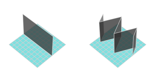
- Each wall is assumed to consist of a uniform material, and be of constant, nonzero width (to ensure this for the zig-zag, we can give it rounded corners).
- We won’t dig the walls into the ground.
- We’re primarily interested in preventing the fence from toppling over due to lateral wind pressure, coming from the side, orthogonal to the length of the straight fence, with some fixed force.
- We aren’t concerned about the fence shifting laterally, sliding along the floor. As a result, we assume infinite friction between the fence and the floor.
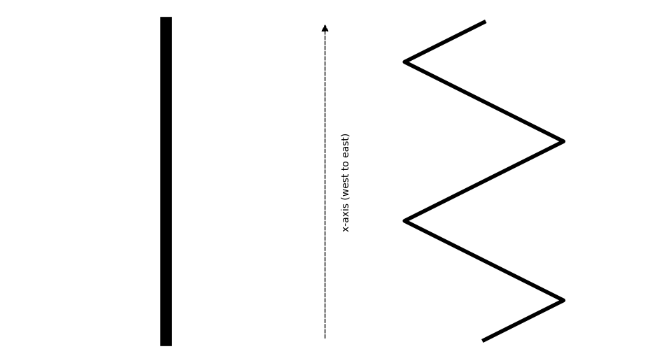
- We’ll only consider fence designs which can be repeated to cover arbitrary lengths (which is our \(x\)-axis), don’t loop back around, and look the same whether we’re building east-to-west or west-to-east (after all, the wind could come from either side).
- All fences must be of fixed height \(h\).
The penultimate condition, mathematically put, means that if we view our fence from above, the curve along the center of the width of the fence should form a mathematical function \(y(x)\) for \(x\) running from \(-0.5\) to \(0.5\), such that \(y\) is a continuous, odd function vanishing at the endpoints of its domain.
Toppling a Straight Fence
At this point, it’s worthwhile to inspect what would even make a fence topple over. We’ve assumed infinite friction, so it won’t slide around. For our straight fence of, say, unit width, why would sufficient wind flip it?
Let’s first consider the head-on/axial view of the fence, if we’re standing east of the fence and looking west into the length of its body.
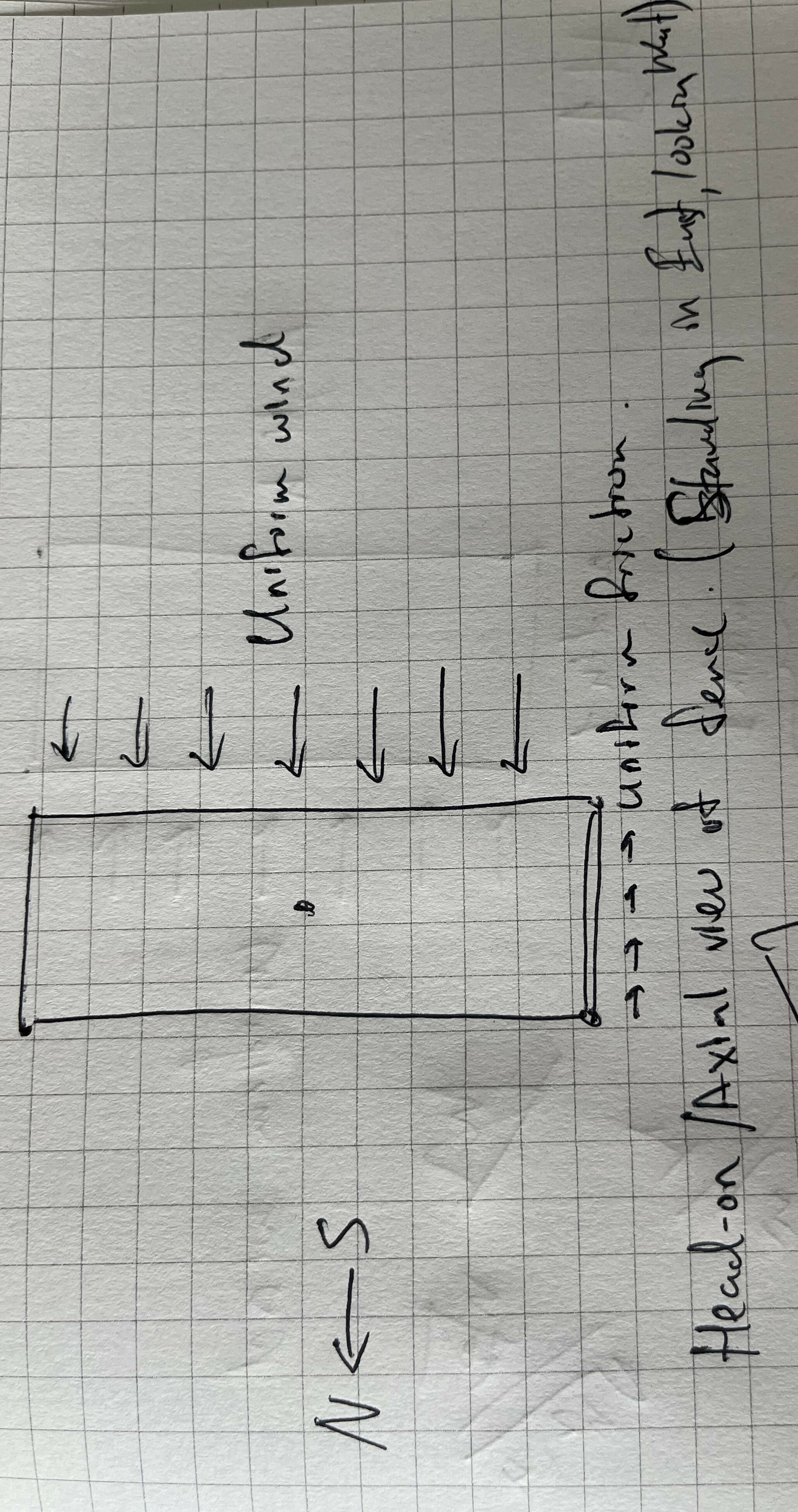
For the fence to topple over, we’d need the fence to rotate counter-clockwise (CCW) about its North edge (with infinite friction and non-deformable material, where else would it rotate about).
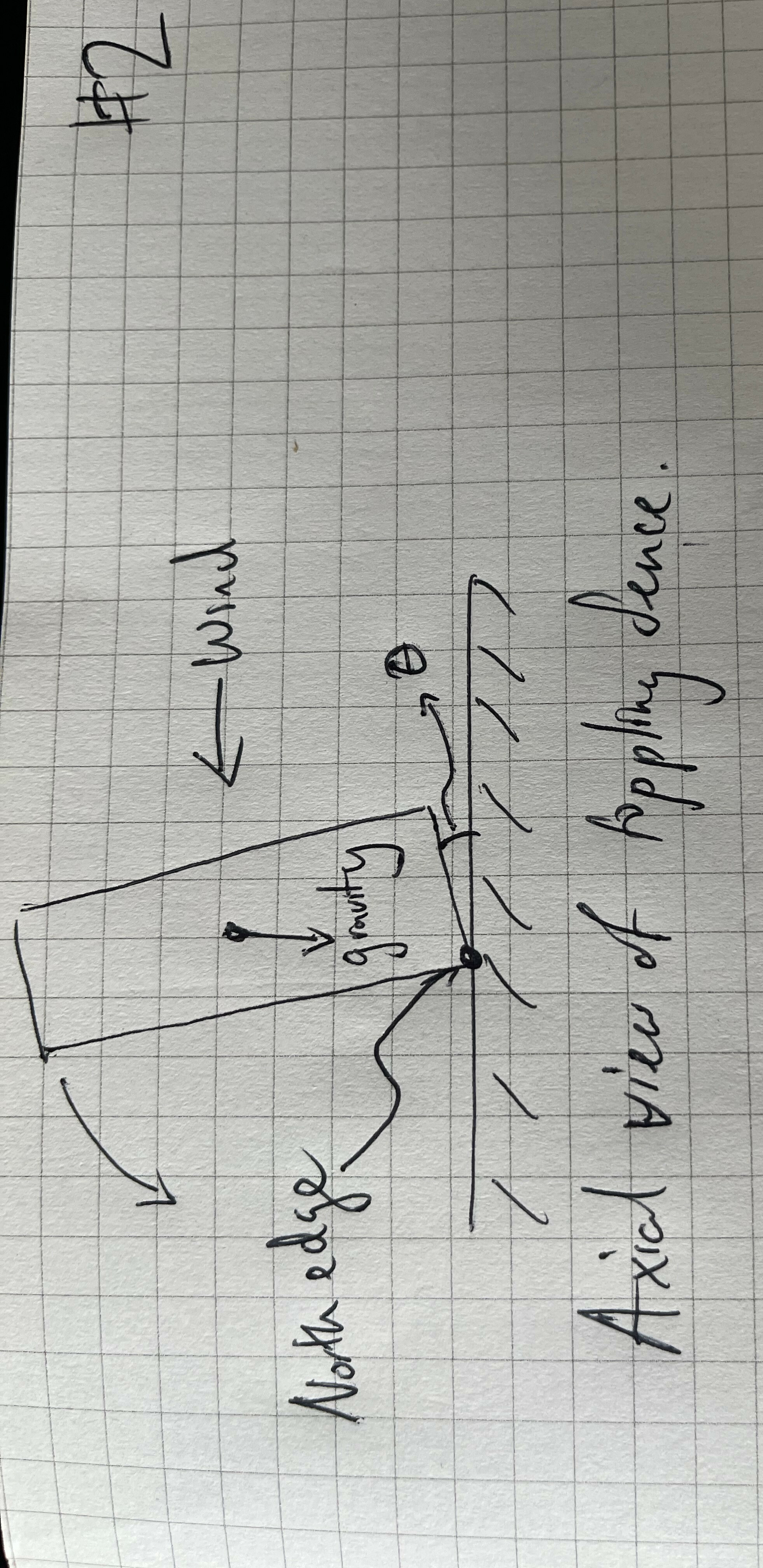
This makes it clear how the fence resists the CCW torque from the wind and friction: via CW torque from gravity. Notice that when \(\theta = 0\), in the untilted case, friction is orthogonal to the instantaneous CCW rotation, so it doesn’t add torque. In the schematic below, I’ll draw it untilted to illustrate the wind and grafvity torques appropriately.
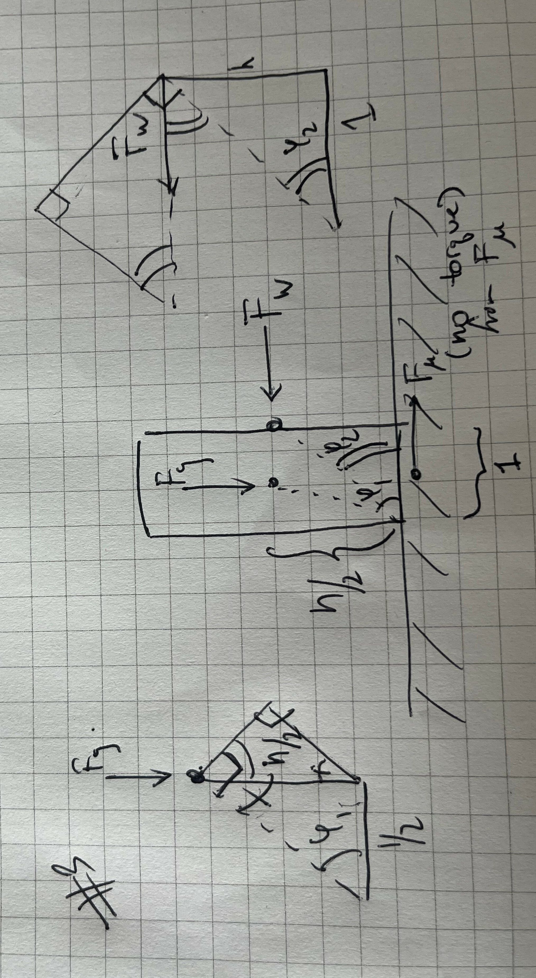
Now we have our final set of torques, for the wind force (which, on average, strikes the center of the south side of the wall), gravity, and friction. The limit point for maximal wind force \(F_W\) our unit-width straight wall can tolerate occurs at equality:
\[ F_g \cos \varphi_1 = F_W\sin\varphi_2 \,\,. \]
Since we know \(\varphi_1=\arctan h\) and \(\varphi_2=\arctan \frac{h}{2}\), we can simplify further to
\[ F_g \frac{1}{\sqrt{h^2+1}} = F_W \frac{h}{\sqrt{h^2+4}}\,\, \]
Rearranging, we have
\[ F_W = F_g\frac{1}{h}\sqrt{1 + \frac{3}{h^2+1}} \]
We see that there’s roughly an inversely proportional between requisite wind force to topple over the fence and height (from inside the square root; note that mass scales with height so the outer \(h^{-1}\) cancels with terms inside \(F_g\)). Makes sense, the taller you are, the easier to topple you. On the other hand, the denser you are, the harder it gets (due to growth of \(F_g\).
Finally, if we derived the above keeping a variable width \(w\) in mind we’d actually end up with
\[ F_W = F_g \frac{w}{h}\sqrt{1 + \frac{3w^2}{h^2+w^2}}\,\,. \]
Toppling a Zig-Zag
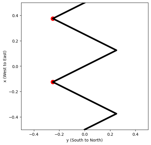
How do things change with the zig-zag fence? Now, the fence would rotate not along the entire North edge, like the straight fence would, but only along two points, highlighted in red below.
We can calculate the torques from the axial view again, but note that this picture may be deceiving! The fence is angled here, so the \(F_W\) incident to it will on average act at the “center” of the \(y\)-axis.
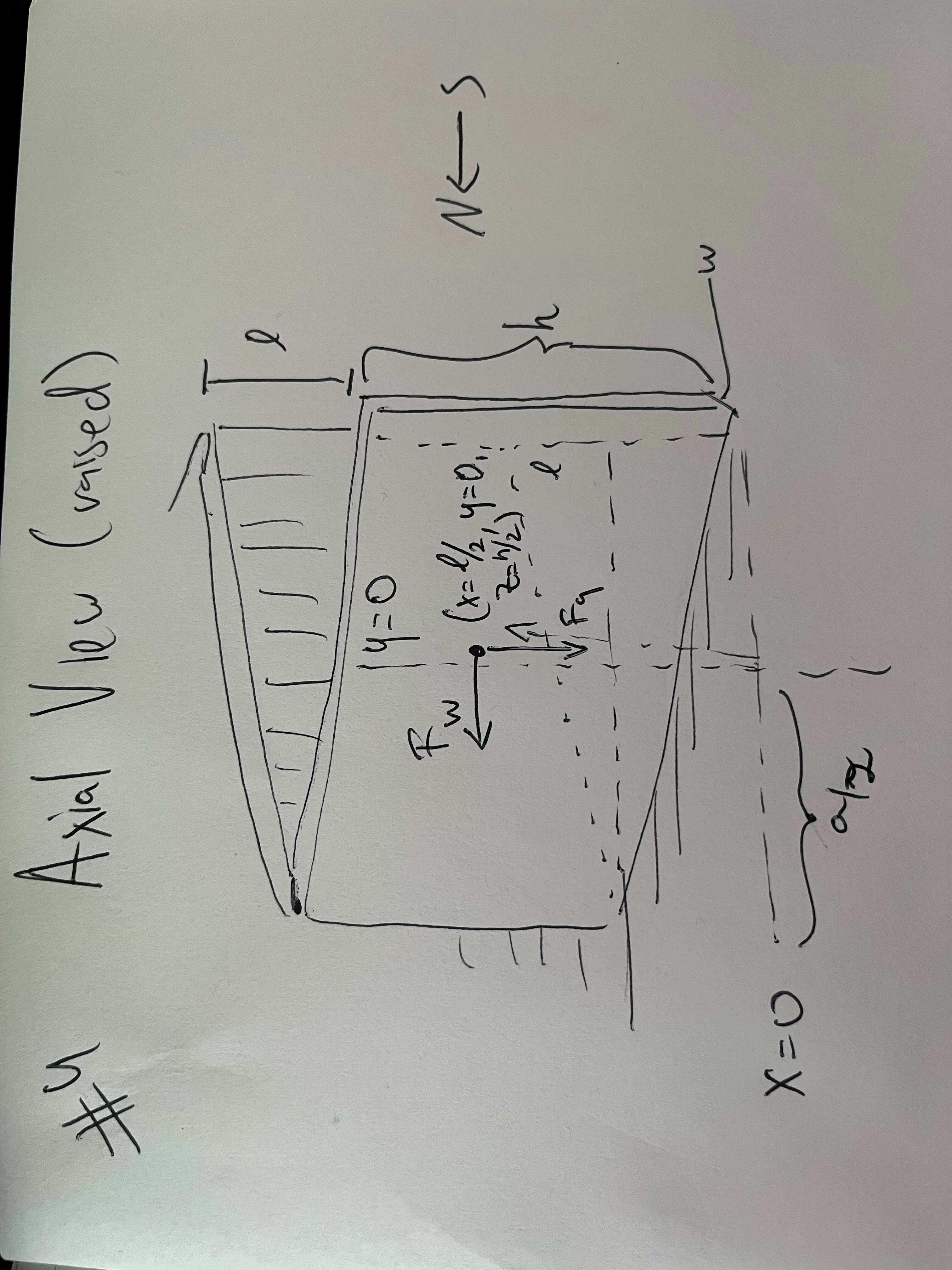
One might worry that because the wind is hitting the fence at an angle, it will be applying less pressure compared to the straight fence completely orthogonal to the wind. And it is! However, there’s correspondingly more fence to hit. Across a fixed length \(\ell\), the total flux of wind hitting the fence is going to be the same, since the orthogonal component to the wind is all that matters. This is not the same as the drag that different fence shapes would have, if they were moving. Note that we’re assuming the fence is long enough here that we don’t have to model the fluid dynamics of the wind wrapping around the ends of the fence.
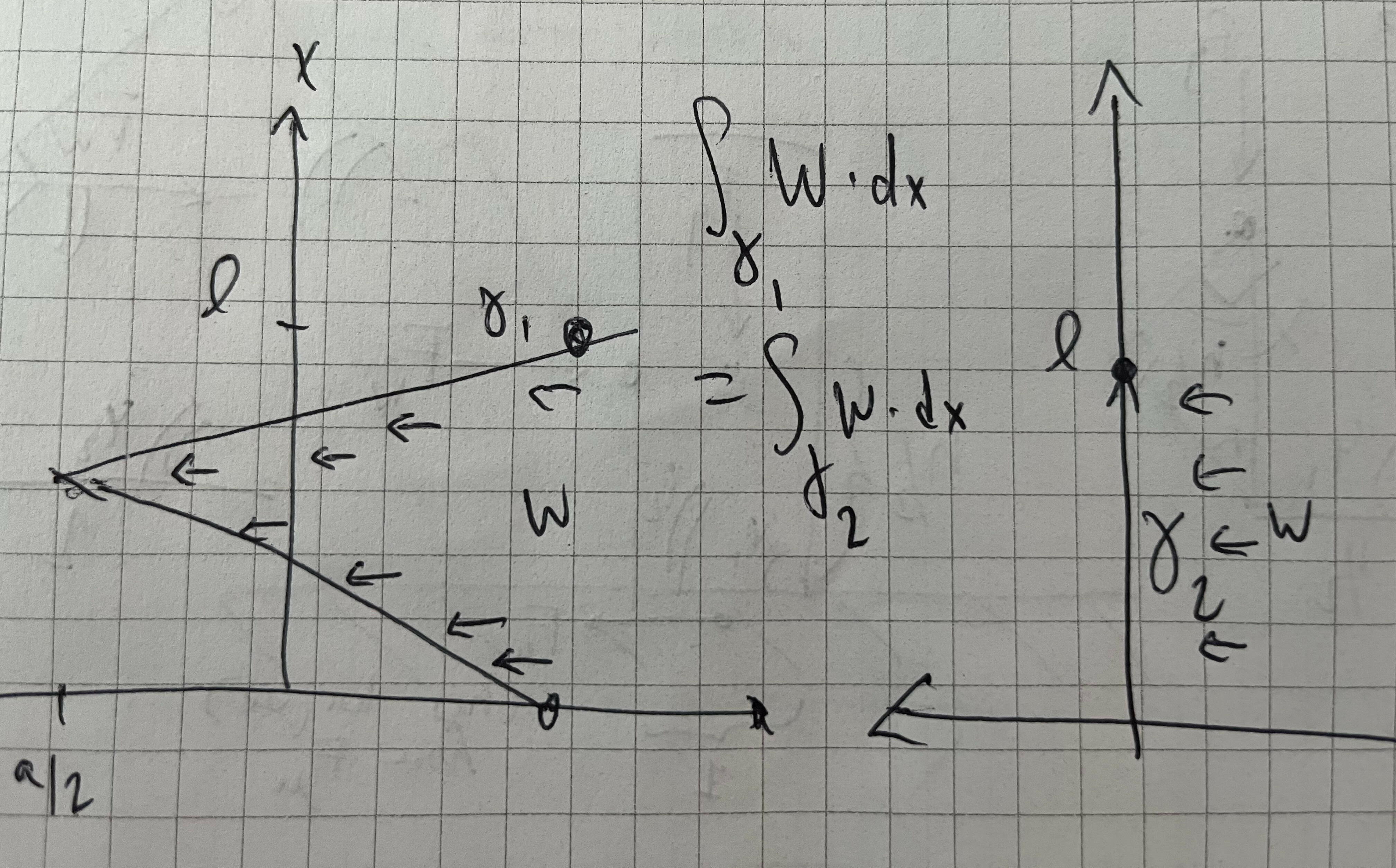
We also note that there’s a lot more going on here, for a given “V” of the zig-zag, the center of mass, by symmetry, will be at \((\ell/2, 0, h/2)\), with the average wind force and gravity both acting there (outside of the material itself, counterintuitively).
Nonetheless, the torque calculation is more or less the same as the flat wall case, besides the fact that the wind is now acting at the center of the axial view, so the torque is acting on a lever of length \(\sqrt{(a/2)^2+(h/2)^2}\), where \(a\) is twice the amplitude of the zig-zag, or its span crest-to-trough. The width of the fence itself (which is now no longer parallel to the \(y\) axis) doesn’t play a role except in helping us calculate the total mass (assuming it’s negligble relative to the amplitude). If anything, the angles cancel out more nicely here.
\[ F_W = F_g \frac{a}{h}\]
Notice the width \(w\) doesn’t play a role here at all (except insofar as it affects the mass of the fence and therefore \(F_g\)).
But if we use the same amount of building material for a length \(\ell\) of fence, so as to equalize the comparison between the zig-zag and the straight fence, the \(F_g\) between the two is the same, we get a directly proportional improvement in maximum withstood wind force and the amplitude \(a\). On the flip side, for a fixed height and mass, the width of the straight fence is also determined, so although \(w\) and \(F_W\) also share a similar nearly proportional relationship, straight fences of a given total mass and density can’t increase their width.
Optimizing the Wall
Given all the above, it’s clear that we could always improve lateral wind resistance by making our zig-zag thinner and amplitude larger.
Furthermore, the shape of the zig-zag didn’t end up mattering much: by symmetry the torque acting upon the center-of-mass is what kept our fence from toppling.
Thus, we’ll assume we must have some minimal thickness that the fence must have, a property of our building material (e.g., brick width). This, in turn, translates to essentially an arc length constraint on our fence shape for a fixed amount of material.
We can thus simplify our optimal wall shape question: given some “period length” to fence off, say from \(x=-1\) to \(x=1\), can we identify an odd, continuous function whose average on \(x>0\) is as large as possible? Then, if the pattern was repeated, this would amount to having the longest lever possible counterbalancing the fence.
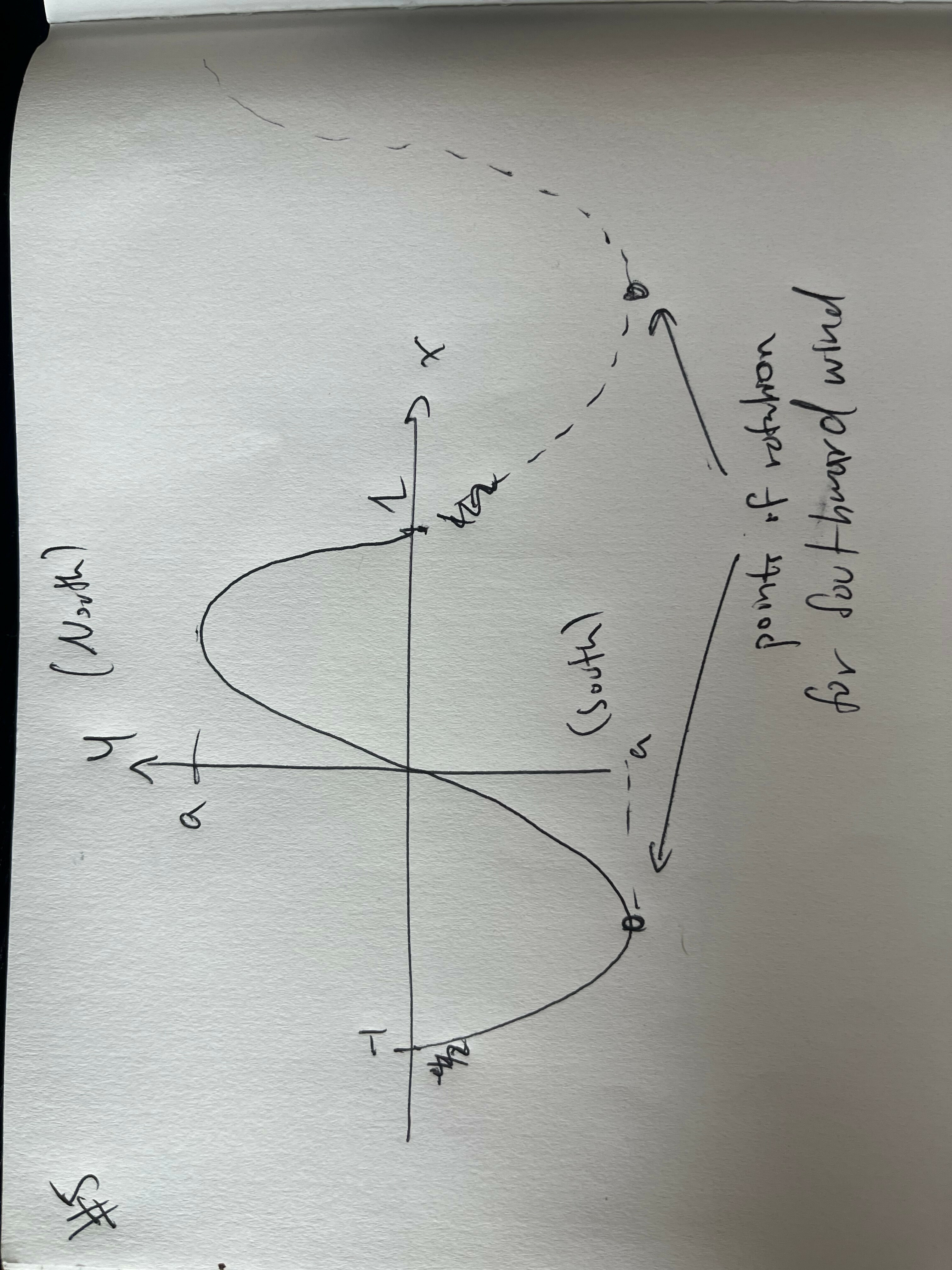
Given the setup above, we don’t even need to think too hard about the shape or bring out variational calculus: a zig-zag is already the most efficient way to reach a prescribed amplitude! Given that, regardless of the shape of the odd function, the center of mass in our statics equations always happens to be across the \(x\)-axis, we should try to reach the largest amplitude possible!
What’s the Upshot?
So now that we know the optimal shape, the question stands, given a straight wall two bricks thick (width \(2w\)), then keeping the same materials, and using a combined catenary wall one brick thick (\(w\)) instead, and the same amount of building material, how much more wind resistance have we earned?
To facilitate numerical computation, let’s imagine our unit of length to cover here is 1 meter, with the requisite height being 1 meter as well. We can then suppose \(w=0.05\) is a reasonable brick width. For the straight wall, the wind force equation is unsurprisingly dominated by \(h\) so it behaves roughly linearly in width (recall this is \(2w\)).
\[F_{W, \text{straight}}\approx 0.1015 F_g\,\,.\]
Given that we’re covering 1 meter of length with a 2-brick-thick straight wall, we can consider our (optimal) alternative of a zig-zag with a total arc length of 2 meters. With a little bit of trigonometry, we can back out that the zig-zag is composed of two opposing isoceles triangles joined at one end, each of which must have sides of length \(0.5\). In this case their base is also \(0.5\) meters long, so it’s actually equilateral (if we were covering a longer stretch of fence, it’d be a pair of obtuse isoceles triangles comprising the zig-zag).
This puts the amplitude at \(\frac{\sqrt{3}}{4}\). Then twice the amplitude gets us the wind force since \(h=1\) per our formula derived in the prior section.
\[F_{W, \text{ zig-zag, equilateral}}\approx 0.8660 F_g\,\,,\]
or, put another way, we’ve engineered a fence over \(8\times\) as strong!
We can ask analogous question. How much thicker would our straight fence need to be to withstand the same force? Here, we’re willing to give it additional mass. Since that scales linearly with width, we’d actually have a nearly quadratic relationship:
\[ F_{W,\text{ straight,wider}}=F_{g,\text{ per unit brick width}}\frac{w^2}{h}\sqrt{1 + \frac{3w^2}{h^2+w^2}} \]
Setting this equal to our zig-zag fence, we find that a thickness of approximately 77 cm is required, or 15 bricks!
A Final Note
One hidden unit factor present in our zig-zag calculations has been the length of fence one curve closes off. In the calculations above, it was a unit meter.
Of course, we could consider covering not just 1 meter with one “zig zag” but several. A longer length that we cover between zigs and zags will, for a fixed amount of building material per unit length, result in more gentle zig and zag slopes (since we only do one zig and one zag per “period”). Many sawtooths in a row is inefficient at reaching the same amplitude.
This leads to other constraints on practicality: can you really maintain a zig-zag shape across such long lengths? Moreover, underlying our torque computations is the fact that the fence is assumed to be a rigid lever. The longer out this math is applied, the less realistic this becomes. That said, the simplistic model is quite helpful. For a particular length of fence, zig-zag, don’t sinusoid!
Special thanks to Tom Hartke who gave this post a physicist’s review!